
Zero Trust for the Home Lab - VLAN Tagging and Firewalls with pfSense (Part2)
- Tenaka

- Jun 7, 2025
- 10 min read
Updated: Nov 10, 2025
What Is Zero Trust - Recap
Zero Trust is a security framework that assumes no user, device, or network segment is inherently trustworthy, regardless of where it sits in the network. The core principles include:
Verify explicitly – Always authenticate and authorize access.
Use least privilege access – Limit access to only what's needed.
Assume breach – Design as if attackers are already in the network.
What's Covered in this Blog
This post covers implementing pfSense Netgate 4200, a cheap POE managed switch, VLANs and point-to-point Firewalls.
How Do VLANS and Firewalls Address Zero Trust
VLAN Tagging: Enforcing Logical Segmentation
Virtual LANs (VLANs) break a physical network into multiple, isolated broadcast domains. Each VLAN behaves like a separate network, even if all devices are plugged into the same switch.
With 802.1Q tagging, VLANs add a tag to Ethernet frames to denote which virtual segment the traffic belongs to. This enables:
Separation of devices by function or trust level (e.g., IoT, guest, management, servers).
Containment of potential breaches, malware on a smart TV can't reach your file server.
Firewalls: Traffic Policy Enforcement
Once VLANs are defined and routed, the firewall rules take over. Each VLAN has its own interface, letting you apply granular, interface-specific policies such as:
Blocking traffic between VLANs by default
Only allowing explicit communication paths (e.g., IoT devices can talk to the internet but not to the LAN)
Logging and monitoring attempts to cross VLAN boundaries
Zero Trust for the Home Lab and pfSense
This marks the first step in a series of technical changes to the home lab. As outlined in Part 1, the goal is to implement a Zero Trust model or get as close to it as possible, while avoiding cloud dependencies and keeping costs to a minimum.
The old Zyxel USG 60W device has finally been retired, it's out of support, no more firmware updates. This is a basic Zero Trust requirement; keep it updated. Its replacement is a pfSense Netgate 4200.
As discussed, one of the key changes is the introduction of 802.1Q VLAN tagging throughout the network. Rather than treating everything behind the firewall as implicitly trusted, I'm segmenting traffic by function: End User Devices, Infrastructure, DNS and IoT. Each VLAN gets its own virtual interface on pfSense, with point-to-point firewall rules and independent DHCP configurations.
This rollout has downstream implications. For starters, the Windows Hyper-V hosts will be updated to support trunked VLANs on the switch and the external Virtual Switch will be assigned the Server VLAN. Each virtual machine will map to a specific VLAN, ensuring that VMs are isolated according to their function and access needs. The pfSense management interface will be moved to a dedicated physical LAN port, isolated from all other LANs and VLANs by firewall rules.
Additionally, the Pi-hole DNS servers and Domain Controllers, which previously sat on a flat LAN, will require some reconfiguration. DNS Forwarders on the DC's will require re-pointing to the new PiHole IP Addresses. In addition, the DC's Sites and Services will require updating.
Setup and Initial Config
With the initial setup complete, I've allocated the following:
Port 1 is connected to the ISP's router
Port 2 to the NETGEAR 16-Port PoE GS316EP Managed Switch.
Port 3 is reserved for the Management interface.

Interfaces and VLANs Overview
The physical interfaces are renamed to their correct designation of WAN, LAN and MGMT.
Create the following VLANs and their tags under Interfaces > VLANs:
Tag 1, default tag for management and assigned to the LAN interface
Tag 10 is for DNS\PiHoles
Tag 20 is reserved for Domain Controllers
Tag 30 is for Member Servers
Tag 40 is for Domain Clients
Tag 50 is for Domain Devices such as Printers
Tag 60 is reserved for SIEM and Monitoring
Tag 100 is for any IOT

Assigned the newly created VLANs to the LAN interface, which is igc2.


KEA DHCP
ISC DHCP is deprecated, despite it being the default option, so swap it out for Kea:
Go to System > Advanced > Networking.
Under "DHCP Options," select "Kea DHCP" as the "Server Backend
DHCP Settings
DHCP is to be enabled for each Interface.
Go to Services > DHCP Server
Under each Interface, "Enable DHCP on LAN Interface"
The LAN interface will remain enabled to support devices that don't natively support VLAN tagging via their web management pages. The risk of losing access to systems like the solar inverter will cause an unwelcome distraction.

Note: There is no DHCP Scope for the Domain Controllers on VLAN 20.
LAN DHCP Scope
IP Range 192.168.0.100 to 192.168.0.200
DNS points to the Internet 1.1.1.1, 4.4.4.4, 8.8.8.8

MGMT DHCP Scope
IP Range 192.168.99.100 to 192.168.99.200
DNS points to the PiHole Servers - 192.168.10.70 and 192.168.10.71

DNS DHCP Scope (PiHole)
IP Range 192.168.10.100 to 192.168.10.200
DNS points to its own PiHole Servers - 192.168.10.70 and 192.168.10.71

Member Servers DHCP Scope
IP Range 192.168.30.100 to 192.168.30.200
DNS points to the Domain Controllers - 192.168.20.245, 192.168.20.247, 192.168.20.249


Domain Clients DHCP Scope
IP Range 192.168.40.100 to 192.168.40.200
DNS points to the Domain Controllers - 192.168.20.245, 192.168.20.247, 192.168.20.249

Firewall Intro
pfSense firewall rules manage separate rules for each interface (LAN, WAN and VLAN) and are processed top-down, meaning the first rule that matches a packet is the one that gets applied. If no rule matches, pfSense blocks the traffic by default.
Now for the fun part: initially, every interface, except for the WAN, was configured with permissive any-to-any firewall rules. This meant all devices could communicate freely across all networks. Once system stability was confirmed and I verified that I hadn't broken the system during the transition to VLAN tagging, the rules were gradually tightened to enforce proper network segmentation. The end result is detailed below.
In keeping with Zero Trust principles, permissive subnet rules were removed, effectively eliminating lateral movement, particularly between individual client systems.
Alias's
pfSense firewall aliases let you group IPs, networks, ports, or protocols under a single name. Instead of writing multiple rules for each item, you create one alias and reference it across your firewall rules, making rule management simpler, cleaner, and easier to update.
For example, create an alias like Mgmt_Consoles with the IPs of all management addresses, then use that alias in your rules instead of listing each IP individually.
I've the following Aliases:
Alias_ClientDevices, for printers
Alias_Clients
Alais_DomainControllers
Alias_MemberServers
Alias_PiHoles
Each has been populated either in the case of the DCs by statically assigned IP's, or by reserving the IP address in DHCP, then updating the corresponding alias.

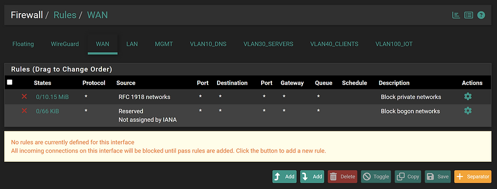
WAN
The default behaviour for the WAN Interface is to block RFC 1918 and Bogon network ranges.
RFC 1918 is a standard published by the Internet Engineering Task Force (IETF) that defines a set of private IP address ranges. These aren't routable on the public internet
These private IP ranges are:
10.0.0.0 to 10.255.255.255 (10.0.0.0/8)
172.16.0.0 to 172.31.255.255 (172.16.0.0/12)
192.168.0.0 to 192.168.255.255 (192.168.0.0/16)
A bogon network refers to a block of IP addresses that should not be seen on the public internet. These are addresses that are either unallocated by IANA or reserved for special use, like private networks or multicast.
Examples of Bogon IP Ranges:
0.0.0.0/8 – “This” network
10.0.0.0/8, 192.168.0.0/16, 172.16.0.0/12 – RFC 1918 private addresses
127.0.0.0/8 – Loopback
169.254.0.0/16 – Link-local APIPA
LAN
The LAN contains the least trusted devices, such as mobile phones, smart TVs, the RoboRock vacuum, and the solar inverter. As a result, none of these devices is permitted to communicate with any other interface, including the Zyxel Wi-Fi router's management interface at 192.168.0.253.
The two allow rules permit communication within the device's own LAN subnet and outbound access to the internet on ports 80 (HTTP) and 443 (HTTPS).
The alias, Mgmt_Consoles is used to block access to each interface’s default gateway on ports 80 and 443. This overrides pfSense’s default behavior, which permits access to the web management interface from all interfaces.

MGMT
The MGMT interface, by design, is allowed to communicate with all other interfaces. I've blocked most management access with the exception of direct connection or via a Member Server.

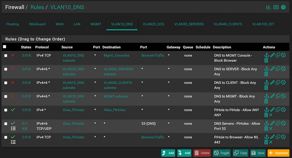
VLAN10_DNS
As with the other interfaces, access to pfSense's Web Management, Servers, MGMT, and Clients VLANs, is explicitly blocked
Aliases for PiHoles are implemented, allowing only named IP's, the 2 devices, from accessing each other from within the subnet.
Outbound DNS traffic (port 53) is permitted to allow name resolution via the Internet.
Ports 80 and 443 are allowed to enable the Pi-hole instances to retrieve updates and patches.
General Approach to Domain Services
The VLANs for DCs, Servers and Clients allow unrestricted traffic between each VLAN. Ideally, firewall rules should be tightened to permit only the necessary services and ports. However, since the plan is to implement IPSec, the effort required to apply stricter rules at this stage aren't justified. IPsec will provide the necessary security controls and require only a couple of ports to be open, and not the plethora of rules required between DCs and Domain members etc.
VLAN20_DCs
The Domain Controllers provide authentication services and therefore require unrestricted communication with client and server aliases, as well as with each other. DNS traffic (TCP/UDP port 53) is allowed between the Domain Controllers and the Pi-hole instances, while port 123 is open to the Internet to support time synchronization services.

VLAN30_Servers
Servers are permitted to communicate with each other, as well as with DCs and Client devices, SCCM makes this a nessessity. The ClientDevice rule also enables support for network printing. Additionally, all servers are allowed outbound access to the Internet on ports 80 and 443 to facilitate Windows Updates.
Note: DC's, Hyper-V hosts, SCCM, SCOM and Certificate services and shouldn't share the same VLANs.

VLAN40_Clients
The clients are exposed to the Internet and susceptible to various attacks during routine browsing and application use. A key principle of Zero Trust is to prevent lateral movement that could be used to discover and escalate privileges.
The following measures are in place to help mitigate this risk:
Client VLAN Isolation:
The client VLAN is configured to block client-to-client communication; no firewall rules permit traffic between hosts within the same subnet.
URA Logon Restrictions:
As outlined in the referenced link below, Server and Domain Admin accounts are explicitly denied logon rights to client machines via User Rights Assignments. https://www.tenaka.net/post/deny-domain-admins-logon-to-workstations
Clients are only permitted unrestricted communication with the DC and the Servers VLANs.
External outbound traffic is restricted to web access on ports 80 (HTTP) and 443 (HTTPS).

Admin Access
The default configuration is for the LAN interface to apply anti-lockout rules to pfSense's management interface.
The rules have been removed in favour of the MGMT interface, so proceed with caution:
Navigate to System > Advanced > Admin Access
Locate the 'Anti-lockout' check box and remove.


Netgear Managed Switch
Of all the devices involved in the VLAN migration, the NETGEAR 16-Port PoE Switch (GS316EP) was the only one that caused real issues. Due to a fatal error on my part, the switch had to be factory reset. Losing the configuration wasn’t a major problem, but diagnosing the loss of access to the switch that led to the reset was frustrating.
The issue stemmed from allowing the switch to obtain its IP address via DHCP. Once the trunk uplink, connecting both pfSense and the switch, was assigned, the switch lost its ability to pick up a DHCP IP address, resulting in a loss of management access. The most likely cause is that VLAN 1 traffic may be dropped as it's explicitly tagged and the switch or router will be expecting untagged traffic.
Assign a static IP address to the switch.

Enable 'Basic 802.1Q VLAN'.

Create the desired VLANs

Assign Truck (uplink) to the following connections:
Port 1 is the connection to pfSense
Port 2 is the connection to the Wifi Access Point
Ports 3 and 4 are the connections to the Hyper-V Hosts
Assign VLAN Tags to the relevant device:
Ports 5 and 6 are for the PiHoles on VLAN 10
Ports 7 through 12 are for Clients on VLAN 40

WIFI Access Point
To assign a VLAN to a Wi-Fi network, you need to configure the VLAN ID directly in the settings of the wireless access point (AP) or wireless controller. These are part of the settings when configuring the SSID and WIFI password.
Manually Set for Windows Client and Server (Non-Hyperv)
To manually tag a VLAN on a Windows machine:
Open Control Panel > Network and Sharing Centre > Change Adapter Settings
Right-click > Properties > go to the Advanced tab.
Look for a setting like VLAN ID, Priority & VLAN, or Packet Priority and VLAN.
Set the VLAN ID you want and click OK.
Once configured, all traffic from that adapter will be tagged with the specified VLAN ID.

Note: Not all NIC drivers support VLAN tagging through Windows natively. Intel, Broadcom, and some Realtek adapters typically do, but it often requires their vendor-specific drivers (not just the Microsoft default). If the VLAN option is missing, you may need to install the manufacturer’s advanced network driver suite.
Hyper-V Servers
The Intel (now ASUS) NUCs are equipped with only a single network interface, which limits the ability to physically separate VLANs across multiple NICs. Meaning Hyper-V management traffic and VM traffic that defaults to the virtual switch go through VLAN 30

To mitigate this, and I certainly don't want Kali on the same interface as my Member Servers is to set the VLANs within the network adapter settings of the individual VM, thus keeping with the Zero Trust approach intact.

Additionally, again deviating from strict Zero Trust principles, the physical hosts serve multiple roles, including File and Print services, as well as DFSR replication.
Raspberry PI and PiHole VLAN
Before moving the PiHoles VLAN, it's important to complete the following steps. VLANs aren't supported out of the box.
Install the latest updates and then the vlan package.
sudo apt update
sudo apt install vlan
Load the 8021q kernel module, which is essential for enabling VLAN tagging on network interfaces.
sudo modprobe 8021q
echo "8021q" | sudo tee -a /etc/modules
Define how VLANs are created and configured.
sudo nano /etc/systemd/network/25-vlan.network

[Match]
Name=eth0.VLAN_ID

[Network]
DHCP=yes
This file instructs systemd-networkd how to create and manage the VLAN interface
sudo nano /etc/systemd/network/25-vlan.netdev

[NetDev]
Name=eth0.VLAN_ID
Kind=vlan

[VLAN]
Id=VLAN_ID
Update the VLAN tagging on the network switch that the Pi's are plugged into.
Restart the network interface.
sudo systemctl restart networking
sudo systemctl status networking
Confirm the IP has updated from 192.168.0.70 to 192.168.10.70.
ip addr showConclussion
Firstly, thanks for following along. There’s a lot of moving pieces and implementing VLAN tagging can present a few challenges. However, this is the first critical step toward achieving a more complete Zero Trust architecture.
Related Posts:
Part 1 - Zero Trust Introduction
Part 3 - pfSense and 802.1x
Part 4 - IPSec for the Windows Domain

Comments